Worm Real-time Tracking
Motion tracking is an essential technique required in numerous real-time imaging applications. For tracking under the microscopic imaging, there are many additional troubles, such as the depth of field (DOF) is strictly in few microns, the object is sometimes full of FOV, and the motion dynamic range requires high. Our work aims to track the freely moving Caenorhabditis elegans for the study of behavioral and neural activities.
As well known, non-invasive imaging to the untethered model organisms is the ultimate means in the analysis of neuronal function. Using the tracking system, researchers who study neurobiology and behavior in C. elegans can build complete neural maps of specific behaviors, like forward moving, mating, feeding and etc. Observing and detecting the aberrant behaviors and neural transmissions of different mutants will also be possible with this system. All the studies above will definitely contribute to our understanding of how worms make a series of behaviors through neural system. Since human nervous system origins in simple worms, medical neurobiology will also benefit a lot from these studies.
In my lab, an excellent in vivo microscope to image the freely moving C. elegans without any constraints and limitations has been implemented under the real time tracking within rapid response, all-time high accuracy and smoothness.
Because the worm body size is around 1 mm, feasible worm tracking can be only implemented in the following way. We calculate the position of neural region of interest (ROI) of worm from the Locomotion and Behavior Imaging (LBI), and compensate the interframe vertical and horizontal offsets by two-axis automated translation stage to recenter the FOV of Neural Calcium Imaging (NCI).
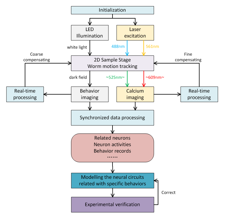
Figure 1 Main flowchart of motion tracking based C.elegans neural activities research.
in vivo Tracking Microscope Implementation
As shown in Figure1, we used a 2-axis Piezo-stage holding a customized fused silica glass dish. Worm is crawling on the top surface of 4mm agarose layer in the dish. In the LBI imaging, 200 fibers coupled from two LED sources were fixed into a reflected ring illuminator, and dark field LBI images were recorded through the agarose layer and a zooming lens. In the NCI imaging, the 488nm and 561nm excitation were provided by two Laser modules and fluorescent images of the worm's neural activities (expressed both calcium indicator GCaMP6s and red fluorescent protein RFP) were recorded under different exposure timing from LBI based on the FPGA synchronization through a Zeiss 20X objective (WD=1.3mm, NA=0.7) and other relay optics into two emission band paths. A high-speed industrial CMOS camera for LBI (~5ms/frame) and two sCMOS cameras for NCI (~3ms/frame) were employed, respectively.
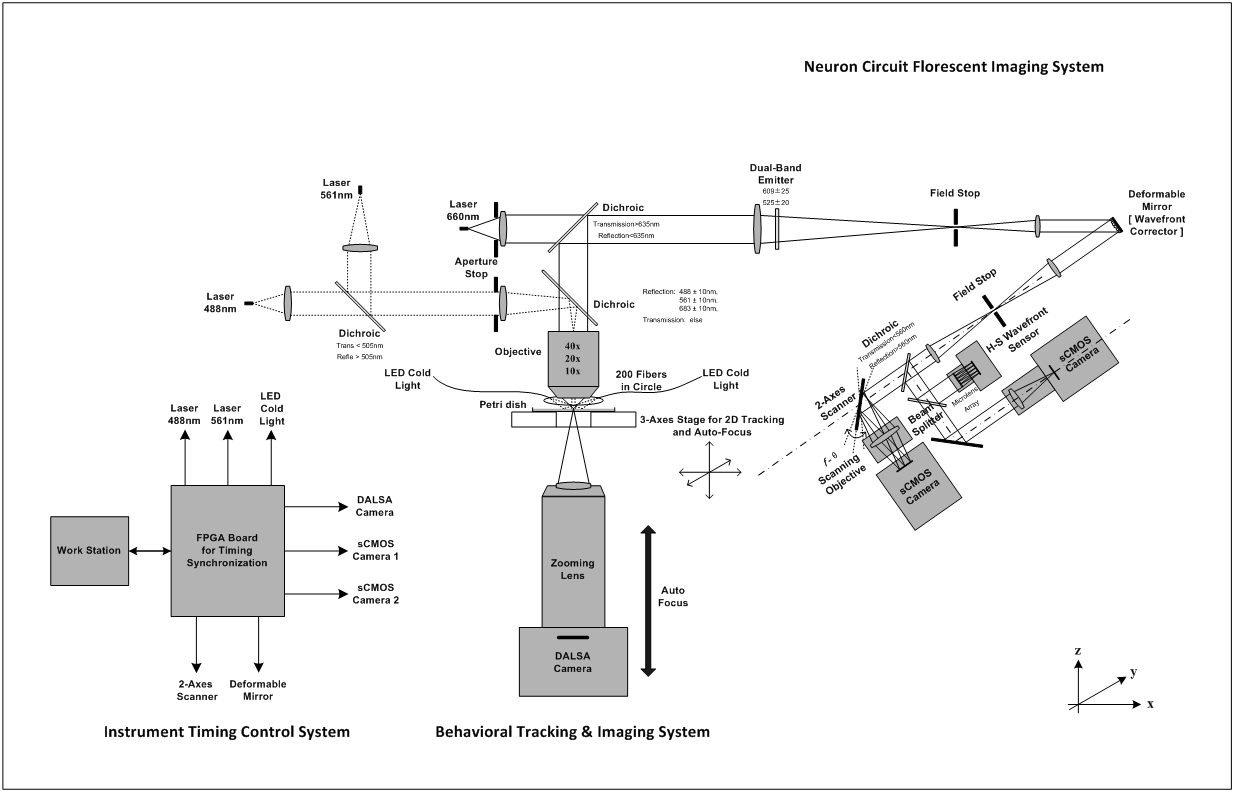
Figure 2 Schematic of in vivo neural circuit tracking microscope for freely moving C. elegans.
Meantime, a two-axis galvo scanner was equipped at the conjugated pupil plane to enhance the frame rate of sCMOS camera being capable of more than 400Hz by spatial multiplexing the full FOV. Moreover, the wavefront corrector and wavefront sensor were located at different conjugated pupil plane, respectively, to eliminate the low-order astigmatism aberrations from above cage system to guarantee the RMS of systematic wavefront errors less than 1/20 waves.
In the system, calculation of worm ROI position in LBI costs nearly 5ms per frame using a self-developed graphical user interface (GUI) written by QT in C++ as well as utilizing OpenGL to real-time display, and calculation errors are normally less than 1 pixel. Besides the Behavior Tracking GUI, the FPGA Timing Control GUI, Multi-source/camera/axis control GUI, and Multi-video Post-processing GUI have been developed for different purposes.
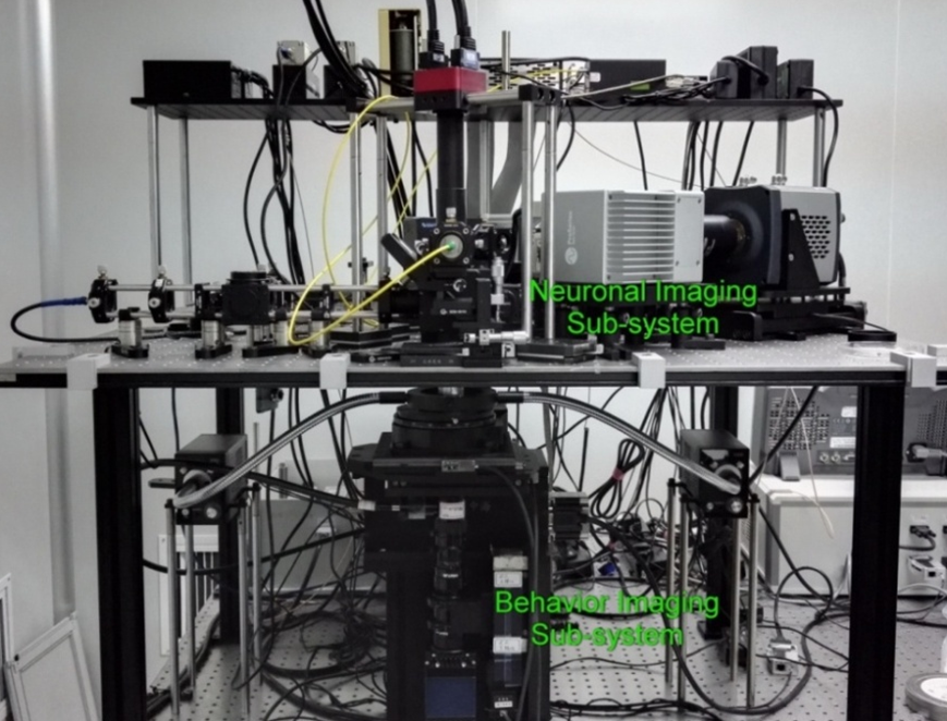
(a) View of the entire system
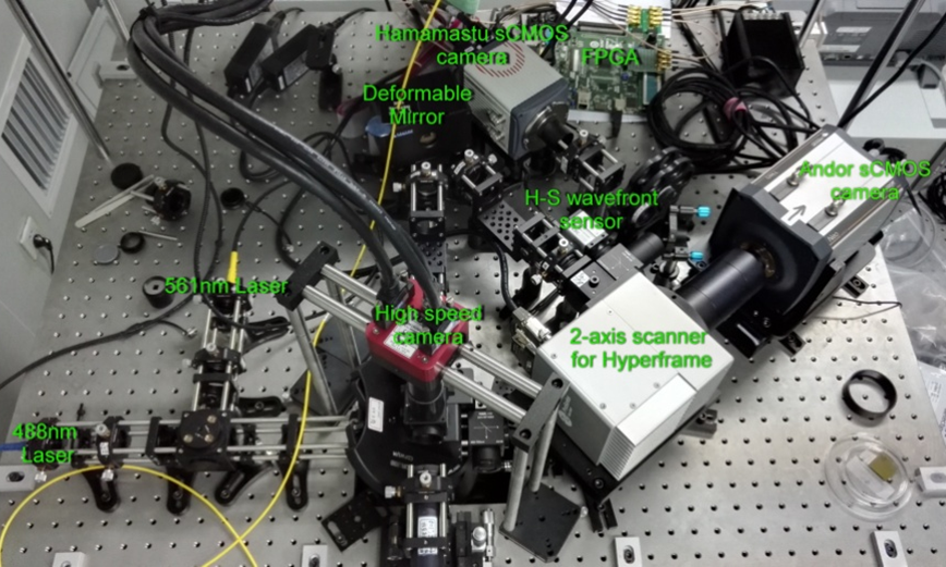
(b) NCI sub-system
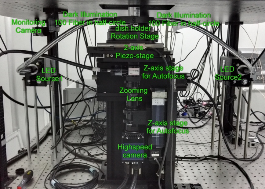
(c) LBI sub-system
Figure 3 Layout of our in vivo tracking microscope
Real-time ROI localization algorithm
From the experimental knowledge, the wild type worm is in 0.8~1.5mm's long and 70-100um's wide. Moderate speed of its freely moving is 200~300um/s.
During the moving, worm's posture is always changing even touching or overlapping to make the topology different, such as in Ω-bend, α-cross, and δ-hide. In our Motion Tracking system, two kinds of worm ROI localization algorithms have been proposed and adaptively used in different postures.
[Skeletonization based ROI localization]
In the algorithm, the centerline of C. elegans has been directly calculated from the segmented worm region. It successively experienced adaptive binarization segmentation, external denoising, region selection, internal denoising, center point extraction, pruning, screening, skeletonization, curve fitting, head/tail recognition and ROI localization.
For extracting the centerline points of the worm body, we define a distance metric as
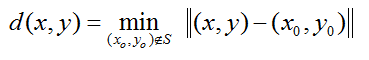
where worm region  is closed,
  .
.
Basing on the distribution of distance metric, Laplacian operation can detect the candidate points along the centerline. Moreover, the maximum distance value could indicate whether the worm body posture is normal. To wrap the distance matrix by a thresholding of half width, this skeletonization based algorithm could still work in the Ω-bend case.
[Optimization based ROI localization]
When the distance value shows abnormal, we attempt an optimization to estimate the centerline via the forward model so that the varied topology of worm body would not affect the result at all. The objective function is given with regular term as
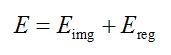
where,  is the image energy term to describe the region convergence,
  is the regularization items which describe the centerline properties.
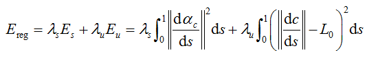
where  and
and  are the smoothness and uniform regularization items of centerline C,
  is the tangent vector of centerline,
  is the length of worm.
In the discrete forward calculation, worm region could be constructed by nearly 200 triangle elements based on the estimated centerline points and width vector from the last localization.
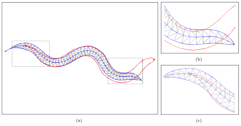
Figure 4 Discrete forward computation. (a) whole body region; (b) details in head; (c) details in tail.
In the iteration, we set the estimated centerline from last localization be the initial value, and adopt the dynamic programming to solve this optimization.
Piezo Stage Based Tracking Strategy
As we known, the vertical and horizontal offsets in tracking loop are basically dominated in latest motion increments of worm. And the actual motion traces of 2-axis piezo-stage for the single step are definitely different under the different axes, different positions, and different PID parameters. It drives us to optimize the tracking strategies to adaptively control the 2-axis piezo stage in every single step closed-loop, as well as the tracking loop.
[1] Adaptively setting proper PID parameters for different axes, positions and steps.
Considering of the high real-time requirements, we establish a look-up table of proper PID parameters for different axes, positions and steps from 5um to 60um at every 5um. And for other step value, nearest interpolation can be adopted. To avoid occupation of another thread for PID control in PC, we implement the adaptive PID control on the controller(Galil), and program on the ROM of the controller to execute in endless loop.
The proper PID parameters for different axes, positions and steps have been given in three steps. Firstly, basing on the readout data from controller, the whole closed-loop piezo motion model has been determined as well as system parameters have been fitted. As shown in Figure 5, there are four process variables can be readout in real-time, and six PID parameters can be reset in real-time. Secondly, the proper PID parameters have been optimized via the model to satisfy the requirements in response speed, step accuracy and motion smoothness. After that, we manually adjusted PID parameters within small ranges based on the actual stage response.
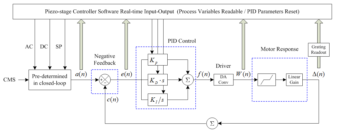
Figure 5 Schematic of the piezo stage single step closed-loop motion model.
[2] Giving a startup thresholding for motion compensation.
[3] Increasing the frame rate of image acquisition and motion calculation.
[4] Executing the two axes motion compensation individually.
As shown in Figure 6, two axes motion are in asynchronous and the execution efficiency would be improved.
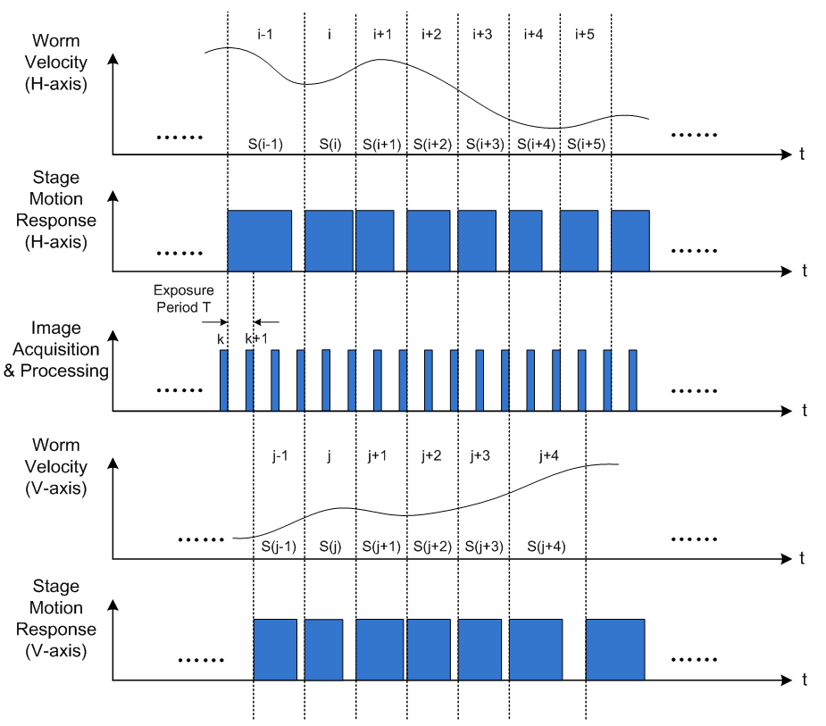
Figure 6 Optimized motion tracking loop for two axes working individually.
[5] Evaluating the tracking performance by trace-simulated tracking experiment.
By analytically representing the real trace of worm ROI moving from the videos in non-tracking mode, as shown in Figure 7, a trace-simulated tracking experiment has been firstly proposed to quantitatively evaluate the tracking performance. The 2-axis piezo motion tracking will be executed as knowing the movement of entire ROI in advance. As the result, the RMS of total tracking errors was around 1 um at 20Hz motion sampling, and the averaged motion responses in H-axis delay and V-axis delay were 58.3ms and 61.1ms.
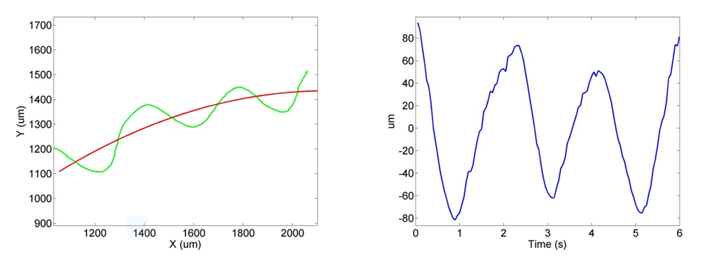
Figure 7 Decomposition of the ROI real trace section in freely moving: (a) ROI real trace in green curve and fitted target curve in red curve; (b) Residual time-variant y-axis components in blue curve.
Behavior Tracking Videos
[1] Freely Moving Centerline Tracking
Frame rate: 24Hz
Exposure time: 5ms
Startup threshold: 5um
ROI position: 0.1 in normalized centerline
2-axis motion: adaptively synchronous
Red cross: FOV center
Green cross: ROI center by calculation
[2] Freely Moving Centerline Tracking with Laser Stimulus
Frame rate: 24Hz
Exposure time: 5ms
Startup threshold: 5um
ROI position: 0.1 in normalized centerline
2-axis motion: adaptively synchronous
Red cross: FOV center
Green cross: ROI center by calculation
Laser Illumination: 488nm, 60mW
Laser Frame rate: 24Hz
Laser Exposure time: 1.5ms
[3] ROI Tracking Mode
Frame rate: 24Hz
Exposure time: 5ms
Startup threshold: 5um
ROI region: head ([0, 0.5] in normalized centerline)
2-axis motion: adaptively synchronous
Red rectangle: ROI
Green cirlce: for Neuronal Calcium Imaging
[4] Overall Tracking Mode
Frame rate: 24Hz
Exposure time: 5ms
Startup threshold: 5um
Overal ROI region: head ([0,0.5] in normalized centerline) & tail([0.5,1] in normalized centerline)
2-axis motion: adaptively synchronous
Red rectangle: ROI
Green cirlce: for Neuronal Calcium Imaging
Neuronal Calcium Imaging Videos
Frame rate: 144Hz (Display Frame rate: 16Hz)
Transgenic worm: Prab-3::nls-RSET-GCaMP6s:SL2:nls-TagRFP::unc-54utr
Objective: C-Epiplan-Apochromat 20x/0.7, WD=1.3mm;
Illumination: 488nm, 70mW;
Exposure: 1.5ms;
FOV: 1024x1024;
Grants
[1] Principal Investigator, High Spatio-temporal Resolution Microscopy for in vivo Neural Circuits imaging, NSFC for Young Scholars, 2012.01-2014.12.
[2] Investigator, High Spatio-temporal Resolution Microscopy for in vivo Neural Circuits imaging, Peking University Scientific Instrument Development Project, 2012.07-2014.12.
[3] Investigator, Frontier Researches and Key Techniques of Cell signal in Temporal and Spatial Dynamics, National Program on Key Basic Research (973) Project, 2011.01-2015.12.
Publications
[1] Heng Mao*, Haiwen Li, Muyue Zhai, Jiazhi Zhang, Xiange Wen, Xuancheng Li, Han Qiao, Shanshan Wang, Tie Zhou, Louis Tao*, High spatio-temporal resolution real-time tracking fluorescent Microscope for the interested neural circuits of freely moving Caenorhabditis elegans, manuscript in preparation.
[2] Haiwen Li, Liang Shan, Shuxiang Dong, Louis Tao*, Heng Mao*, Real-time Motion Tracking of Freely Moving Caenorhabditis elegans via Two-axis Piezo-stage, Biomedical Optics Express, Submitted.
[3] Heng Mao, Xuancheng Li, Haiwen Li, Louis Tao, Tie Zhou*, Active Contour Model based centerline tracking algorithm for freely moving Caenorhabditis elegans, SCIENTIA SINICA: Mathematica, 46(7), 2016.
Patents
[1] Heng Mao, Louis Tao, Ming Jiang, A Neural Circuit in vivo Imaging System, Utility Model, No.201320368802.9, Licensing Date Nov 27, 2013.
[2] Heng Mao, Louis Tao, Ming Jiang, A Neural Circuit in vivo Imaging System, Invention, No.201310255101.9, Licensing Date Mar 16, 2016.
[3] Heng Mao, Louis Tao, Han Qiao, Xuancheng Li, Ming Jiang, A Real-time Tracking System for Neural Circuit of Caenorhabditis elegans, Invention, No.201410117593.X, Licensing Date Aug 31, 2016.
Software Copyrights
[1] Heng Mao, Louis Tao, 2D Real-time Tracking System for Neural Cuicuit of Caenorhabditis elegans, Peking University, V1.0, application date May 26, 2016.
[2] Heng Mao, Louis Tao, Multi-Source, Multi-camera and Multi-axis Control High Speed Synchronized Imaging System, Peking University, Multi-SOCAS, V1.0, application date Oct 12, 2016.