Multi-modality tomography system setup (2009-2011)
Since 2009, I have modified a commercial 2D multi-modality imaging facility (in-vivo FX Imaging System, Carestream Health, Inc.) and transformed it into a 3D tomography system. By implementing automatic two-axis scanning mechanism, performing well geometric alignment and calibration, manipulating devices (X-ray source, motorized stages and camera) in our programmed GUI (Graphic User Interface) and fabricating physical phantoms, the complete projection data of XCT (X-ray computed tomography) have been sequentially acquired and reconstructed to validate our algorithms under the two-circles-plus-one-line trajectory, which is applied to the limited space scanning XCT.
In addition, by collimating the NIR (Near-infrared, 780nm) Laser beam and shooting on the up-surface of phantom, as shown in Fig.1, this modified system became a bi-modality tomography system including XCT and DOT (Diffuse Optical Tomography).
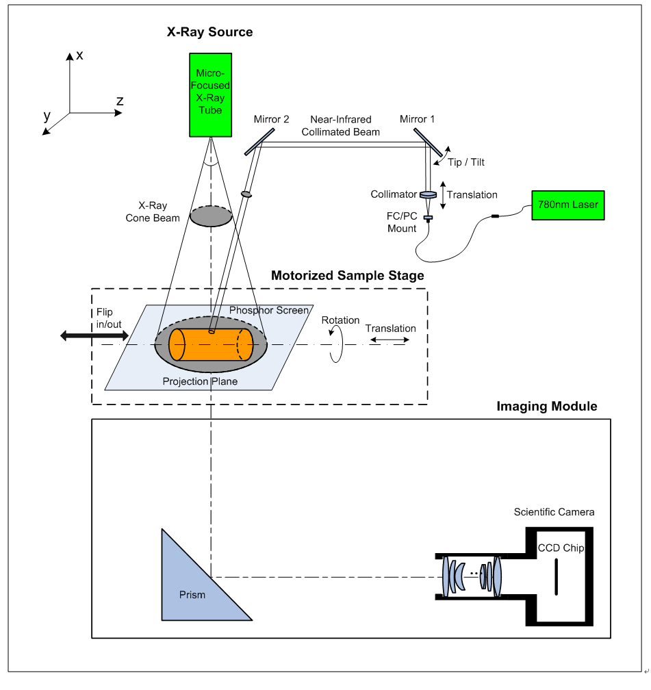
Fig.1 Modifications on the 2D multi-modality imaging system
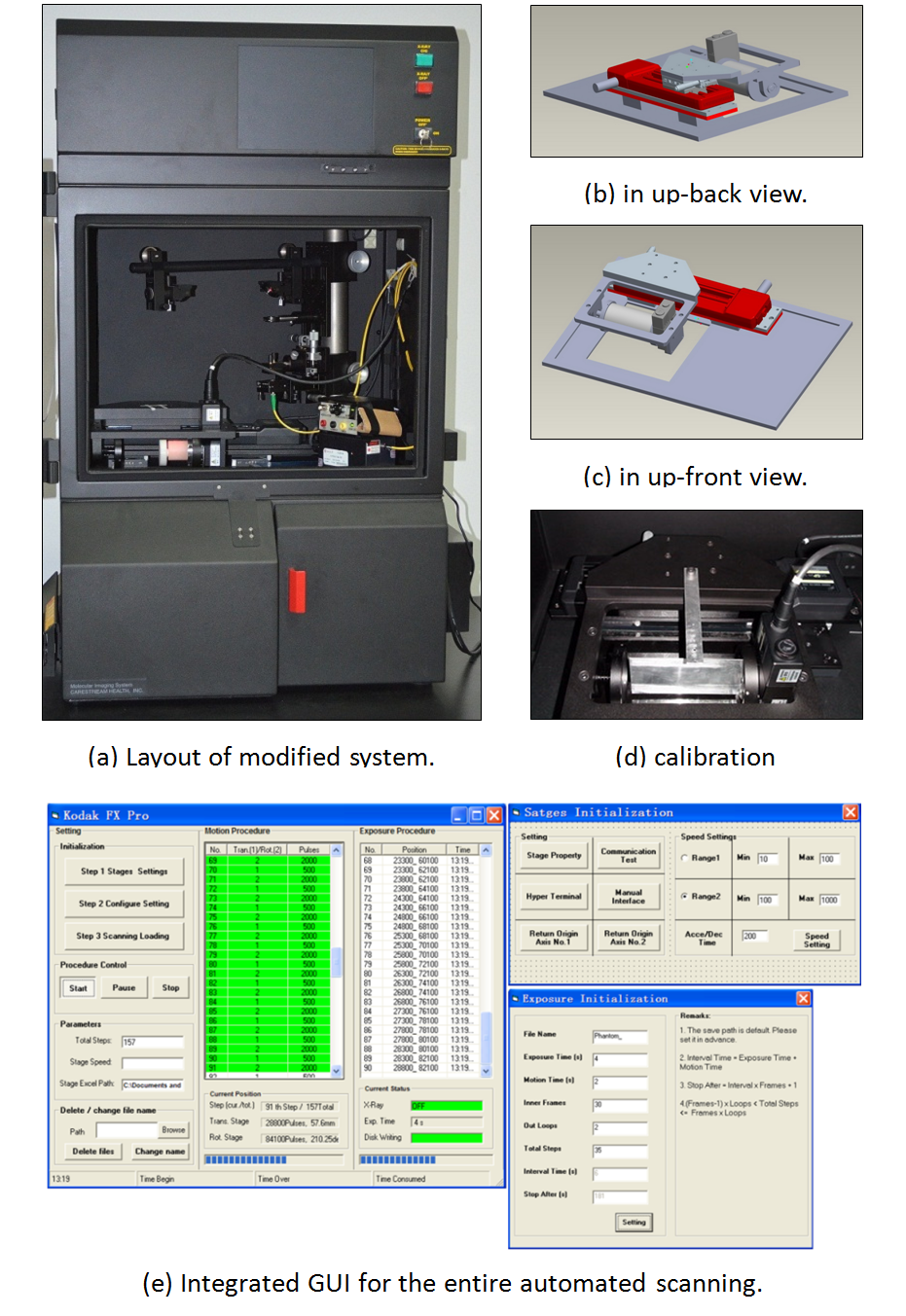
Fig.2 Hardware and software of modified 3D tomography system
Geometric calibration for XCT (2012-2013)
Different from the 2D imaging system, the 3D tomography imaging is fully dependent on the system coordinates and geometric parameters inside. For this reason, a multi-scale alignment and calibration for the cone beam XCT in our system have been performed as shown in Fig.3. In the procedure, a concentric hollow cylinder and a thin aluminum sheet with pre-defined pinhole pattern have been fabricated and employed as the references in different calibration steps. Basing on our XCT system and above calibration results, the exact XCT reconstruction has been demonstrated in the single pixel sampling level [1].
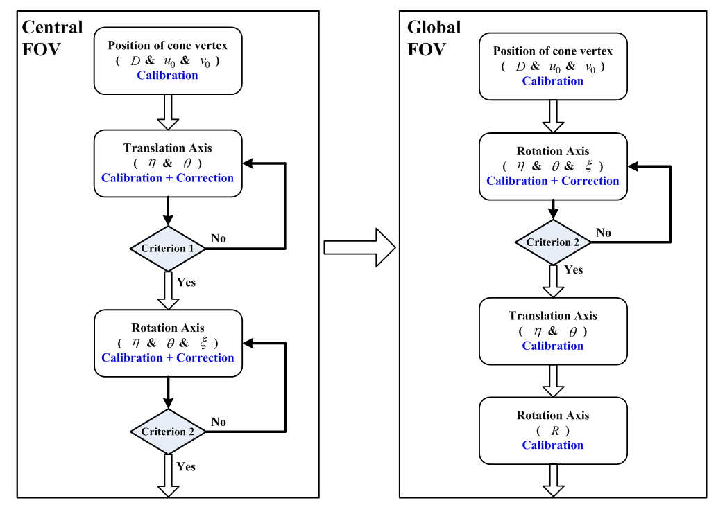
Fig.3 Flowchart of multi-scale alignment and calibration.
BLT Reconstruction algorithm (2012-2013)
Meantime, I have proposed a generalized hybrid algorithm for BLT (Bioluminescence tomography) based on the graph cuts algorithm and gradient-based algorithms [2]. The simulation results are as shown in Fig.4. In this hybrid algorithm, the graph cuts algorithm is adopted to estimate a reliable source support without prior knowledge, which successfully gets rid of the support assumption in former BLT algorithms and remarkably enhances the stability of reconstruction. After then, different gradient-based algorithms are sequentially used to acquire an accurate and fine source distribution according to the reconstruction status. Furthermore, multilevel meshes for the internal sources are used to speed up the computation and improve the accuracy of reconstruction.
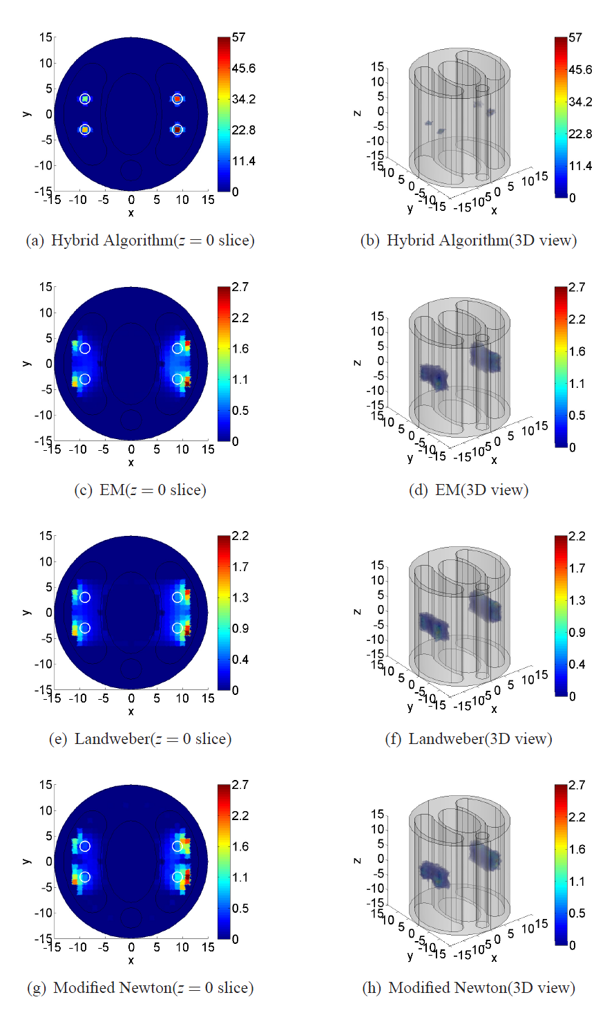
Fig.4 Reconstructed results of proposed hybrid algorithm, EM, Landweber and modified Newton algorithm, respectively.
Practical troubles of DOT (2013-2014)
When doing the DOT acquisition, some practical troubles have been faced. At first, how can we accurately determine the desired shooting direction of laser beam under the XCT coordinates? Secondly, how can we calibrate the conversion ratio of imaging system between the absolute intensity at the bottom-surface of phantom and gray-level data from the camera output?
After many tentative reconstructions, for example to estimate the above parameters during the reconstruction, we found the reconstruction needed to know these parameters in advance otherwise it would hardly work out.
Proof-of-principle DOT system (2015-2016)
In order to improve the bi-modality tomography and develop the joint reconstruction algorithm with XCT and DOT, I have implemented a proof-of-principle DOT system recently, as shown in Fig.5 and Fig.6. Depending on this system, we expect to validate our DOT reconstruction algorithm and analyze the influences of different parameter errors.
In the system, I used the telescope system to shrink the collimated beam aperture (~1mm), used the beam splitter and power meter (Thorlabs) to measure the power variation in real-time, used two-axis scanner (Cambridge Tech) to accurately control the direction of laser beam (OZ optics), and adopted the FPGA board (Xilinx) to synchronize the timing of laser, scanner and camera (Pointgrey). Basing on the camera detector array, the DOT tomography coordinates could be established.
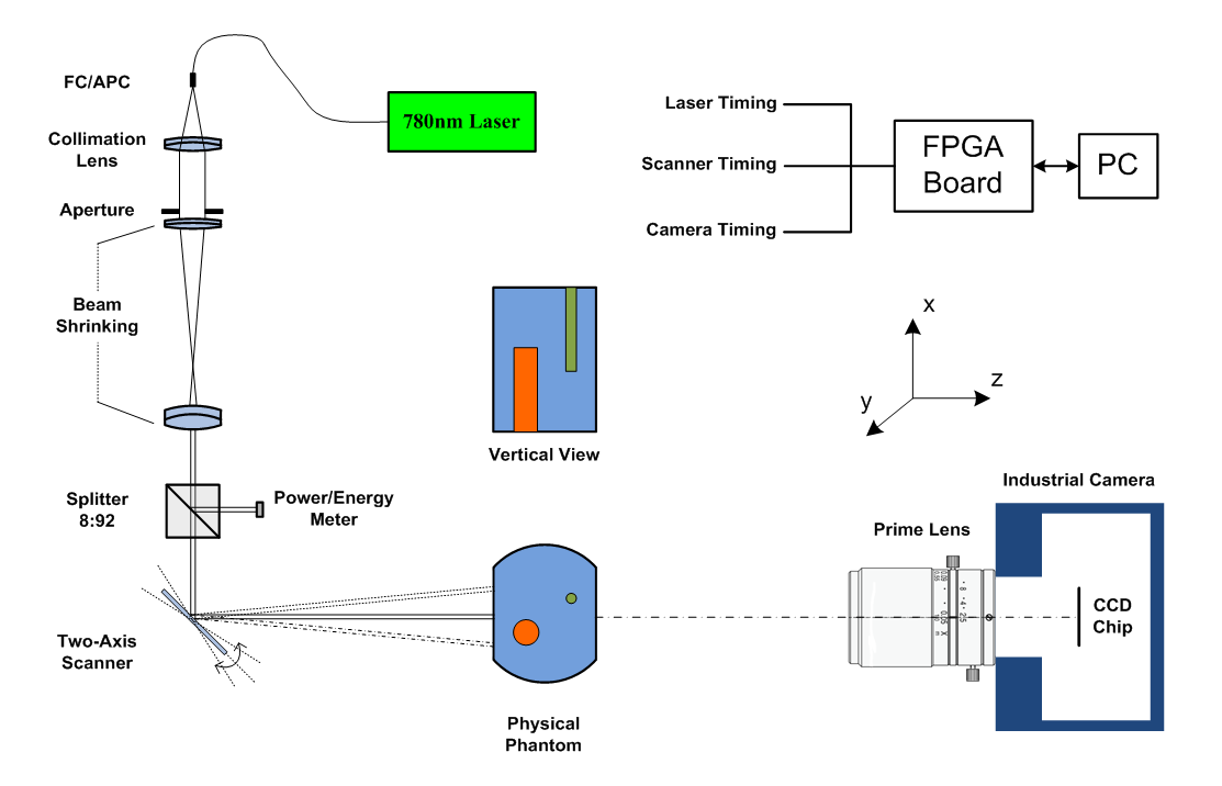
Fig.5 Schematic of our DOT validation system.
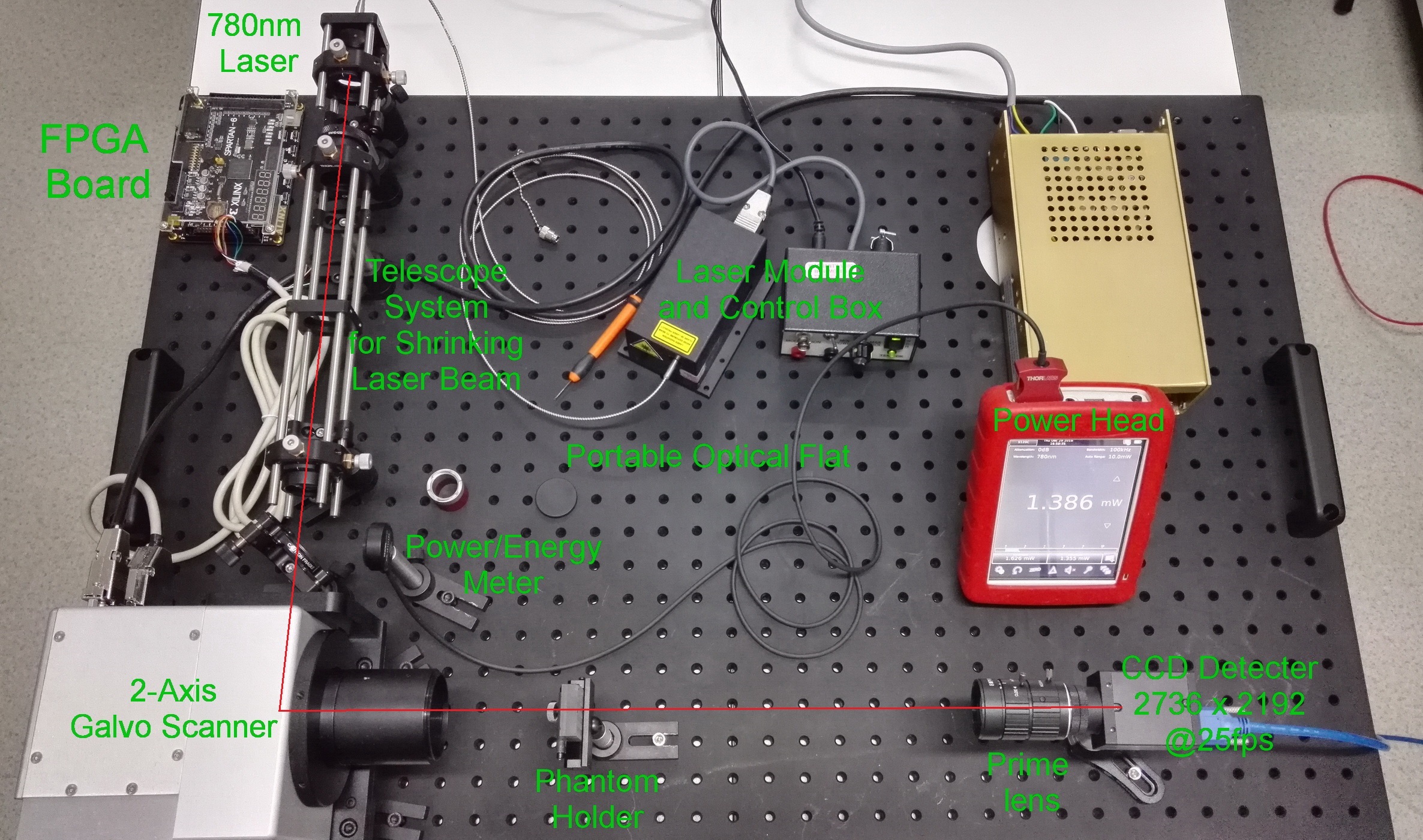
Fig.6 Layout of our DOT validation system.
Fabrication of bi-modality phantom (2016-2017)
Meanwhile, we have completed the fabrication of bi-modality solid phantom components. We used the epoxy resin and its hardener with different proportions of diluted India ink and titanium oxide (TiO2) to make the different components, as shown in the following table. Here, the India ink acts as an absorber and the titanium oxide acts as a scatterer. Five different components have been used to assemble the solid mixture phantom, as shown in Fig.7.
| No. | Epoxy resin (g) | Hardener (g) | India ink(ml) | TiO2 (g) |
| 1 | 66 | 22 | 0 | 0.1 |
| 2 | 66 | 22 | 0.05 | 0.3 |
| 3 | 66 | 22 | 0.10 | 0 |
| 4 | 66 | 22 | 0.15 | 0.2 |
| 5 | 66 | 22 | 0.20 | 0.4 |
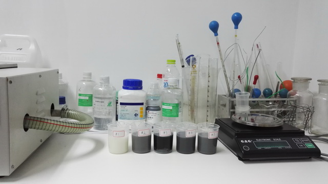
Fig.7 Five phantom components and fabrication materials and tools.
From a large number of experiments, making process of resin components is summarized as follows:
[1] Slowly pour the epoxy resin (66g) and hardener (22g) into a beaker. Try to prevent bubbles initially.
[2] Use a pipette to instill the dilute India ink into the beaker, letting the pipette tip close to the solution surface so that India ink will not spill and fewer air bubbles will be introduced.
[3] Add the titanium oxide and put the beaker into the water bath heating and slowly mixing with a glass stirring rod. The initial temperature of the water is set as the room temperature (22℃-25℃) and the ultimate heating temperature is set as 40℃. The glass stirring rod should not be too thin that materials are not able to be mixed well before curing. The diameter of the glass stirring rod we use is 5mm. After slowly stirring around 35-40 minutes, the material should be mixed well and the solution starts turning thick.
[4] Stop stirring and let the beaker stand in the water bath for 10 minutes to degas.
Cure the phantom in room temperature water to prevent it from foaming up. The curing time is no less than 6 hours.
[5] After these components were hardened, they have been machined into the desired shapes and assembled as a complicated phantom we want. Remember to fill and seal the interval of each border with water to prevent the discontinuous distribution of refractive index inside the phantom.
Parameter calibration for DOT (Present)
Now, we are trying to
[1] Control the position of laser beam on the front-surface of phantom by GUI programming;
[2] Record the absolute power at every image exposure;
[3] Calibrate the distance between scanner and the front surface of phantom;
[4] Calibrate the magnification of camera imaging at back surface of phantom;
[5] Calibrate the two scanning axes about their angles to the vertical and horizontal direction of detector;
[6] Calibrate the absorption coefficients and scattering coefficients of different components in quantitative.
Joint reconstruction with XCT and DOT (Later)
[1] Acquire the complete data of DOT, automatically;
[2] Validate the proper DOT reconstruction algorithm and analyze the feasibility of reconstruction without knowing system parameters in advance;
[3] Basing on the XCT acquisition data, develop the joint reconstruction algorithm.
Grants
[1] Investigator, Multi-modality Tomography System and its Reconstruction, NSFC General Program Project, 2009.01-2011.12.
[2] Investigator, Key Mathematical Problems in Information Processing, NSFC Major Program Project, 2010.01-2013.12.
[3] Investigator, Feature based bi-modal image reconstruction, Sino-German Center, Joint Sino-German Research Project, 2015.03 ~ 2018.03.2018.03.
Publications
[1] Yanbin Lu, Jiansheng Yang, John W Emerson, Heng Mao, Tie Zhou, Yuanzheng Si, Ming Jiang, Cone-beam reconstruction for the two-circles-plus-one-line trajectory, Physics in Medicine and Biology 57(9): 2689 - 2707, 2012.
[2] Shengkun Shi, Heng Mao*, A generalized hybrid algorithm for bioluminescence tomography, Biomedical Optics Express 4(5): 709-724, 2013.
Patents
[1] Heng Mao, Jiansheng Yang, Yanbin Lu, Yuanzheng Si, Yu Zhou, John W. Emerson, Tie Zhou, Ming Jiang, A Multimodality in vivo Tomographic Imaging System, Invention, No.201010299375.4, licensing date Jun 13, 2012.